Bridge Load Capacity: How Much Weight Can a Bridge Hold?

How Much Weight Can a Bridge Hold?

There is no single weight capacity for every bridge. A bridge's load capacity depends on its structural design, span, materials, foundations, intended use, load distribution, and the specific design criteria established by the project's engineers.

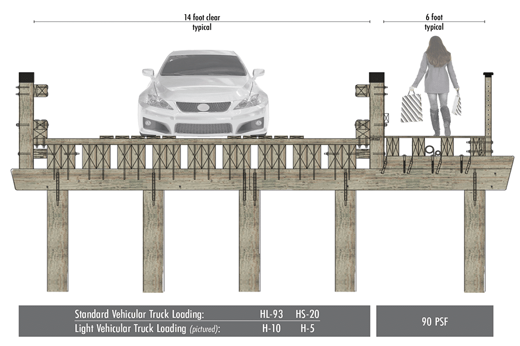
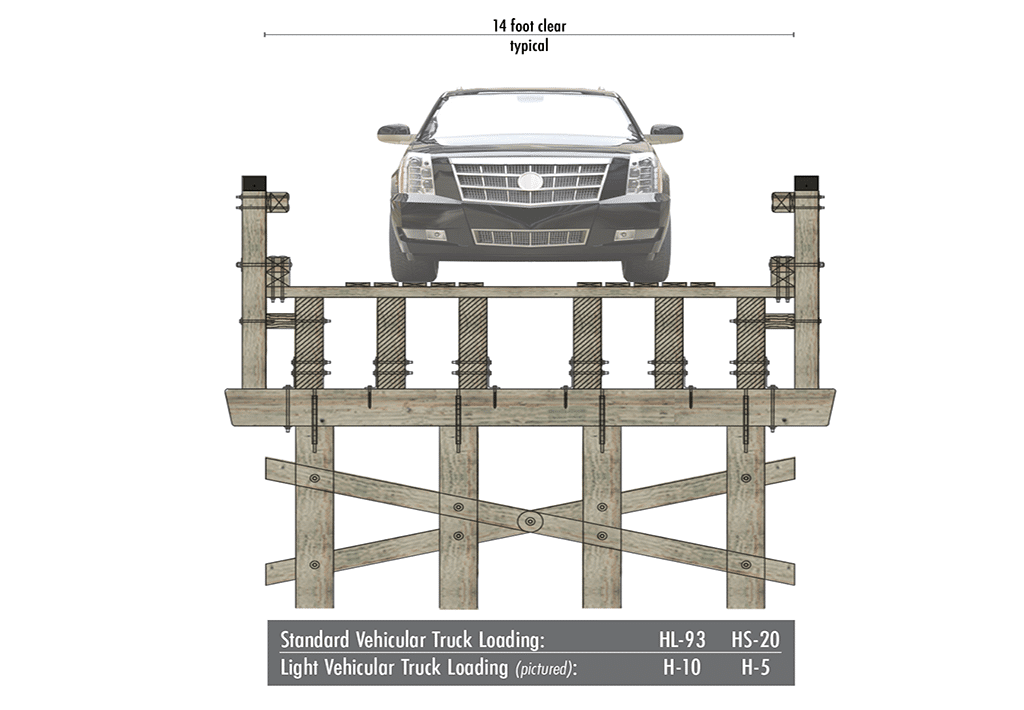
Pedestrian bridges are commonly designed around loads expressed in pounds per square foot (PSF), while vehicular bridges may be engineered around standardized loading criteria such as H5, H10, HS20-44, HL-93, or project-specific vehicle and equipment loads. The appropriate bridge load should be established based on anticipated regular use, occasional or emergency use, applicable standards, and future requirements.

What Is Bridge Load Capacity?

Bridge load capacity refers to the loads a bridge is engineered to safely accommodate under defined design conditions. These loads can include the weight of the bridge itself, pedestrians, vehicles, equipment, environmental forces, and other project-specific demands.

Bridge capacity cannot always be represented by a single maximum weight. Vehicle configuration, axle loads, axle spacing, load distribution, span, structural configuration, and other engineering factors can influence how a bridge responds to a given load.

What Units Are Used to Measure Bridge Capacity?

Bridge capacity can be expressed using different measurements depending on the type of load being evaluated. Rather than relying on one universal "bridge capacity" number, engineers evaluate how different loads are applied to the structure.

Pounds (lb.) describe individual concentrated loads, including vehicle axle loads.

Kips are commonly used in structural engineering, with one kip equal to 1,000 pounds.

Tons may be used to communicate the approximate gross weight of vehicles or equipment.

Gross Vehicle Weight (GVW) represents the total weight of a vehicle and its load.

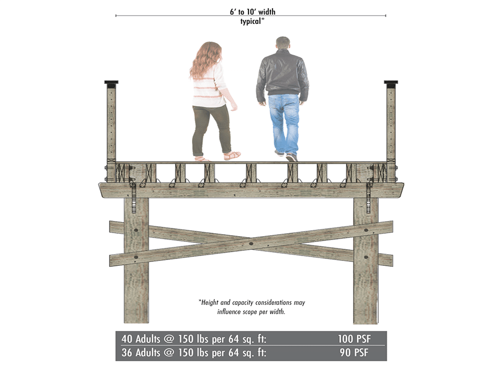
Pounds Per Square Foot (PSF) are commonly used to express pedestrian live loading across the bridge deck.

Pounds Per Linear Foot (PLF) can describe distributed loading along a length, such as the uniform lane-load component shown in YBC's HL-93 loading resources.

Bridge capacity isn't just about total weight. How that weight is distributed can be equally important.

Gross Vehicle Weight vs. Axle Loading

Gross Vehicle Weight (GVW) represents the total weight of a vehicle and its load. However, two vehicles with similar gross weights can place very different demands on a bridge depending on how that weight is distributed.

Axle loading describes the portion of the vehicle's weight transferred through each axle, while axle spacing describes the distance between those loads. Both can influence how forces are distributed through the bridge structure.

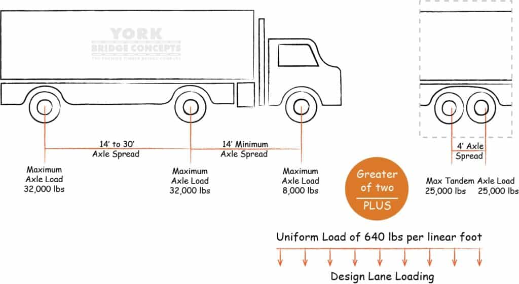
This is why YBC's loading diagrams show more than the total vehicle weight. They also illustrate axle quantity, individual axle loads, and axle spacing to provide a more complete picture of the loading condition.

Designed & Built For Your Requirements

Timber Bridge Load Capacities are one of the most important factors when it comes to building any type of bridge. However, we are here to dispel the myths that timber bridges aren't as strong as alternative building materials. Here are the crucial considerations when it comes to planning your next crossing.

I Didn't Know A Timber Bridge Could Do That!

Most people don’t know about road ratings or loading capacities - we get that. Lots of people underestimate timber bridges - we know that. So to save you a challenging web search, time, and maybe even some money, we made this webinar for you! This session will outline both vehicular and pedestrian use that timber bridges are great for AND give you access to guideline resources on how you can determine what capacity might be necessary for your next project. From accommodating highway standards to some supersized requests for powerline companies, mining facilities, and construction equipment, we’ve got projects that’ll make you say, “I didn’t know a timber bridge could do THAT.”

Learn More In This Pre-Recorded Webinar

Standard Vehicular Loading Diagrams

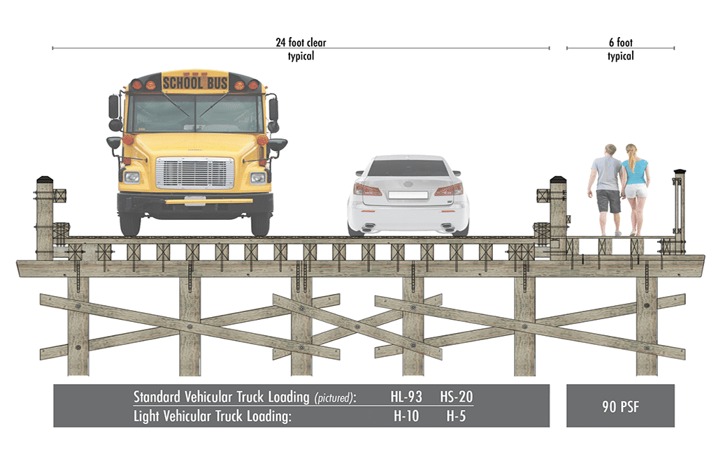
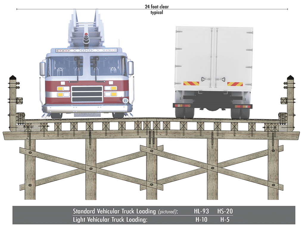
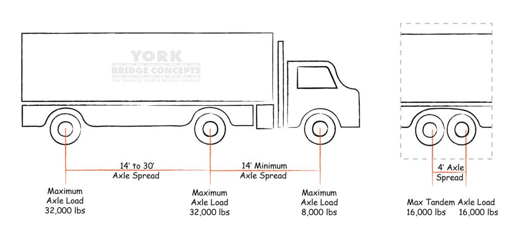
This category is based on regular usage of the bridge by vehicles up to a semi-tractor-trailer. The most common loading capacity for Standard Vehicular Use is the HS20 Truck Loading. They are typically utilized for private and public roadways. Ultimately, a loading capacity is determined by the largest vehicle for anticipated regular use. The HS20-44 design vehicle uses a standardized three-axle loading configuration with a gross vehicle weight of 72,000 pounds. Bridge design considers how those axle loads and their spacing affect the structure rather than treating 72,000 pounds as a universal maximum bridge capacity. To see more about HS Truck Loadings for maximum weights and weight distribution see the associated loading diagrams and charts.

Load Capacity Axle Quantity Axle Spread Gross Vehicular Weight (GVW) Per Axle Loading
HS20 3 axles Min 14' axle spread, 14' to 30' variable axle spread 72k lbs /36 Tons 8k lbs - 32k lbs
HL93 3 axles Min 14' axle spread, 14' to 30' variable axle spread 72k lbs /36 Tons + 640 lbs per linear foot of uniform loading 8k lbs - 32k lbs - 32lbs + 640 lbs per linear foot of uniform loading
What Is HS20-44 Bridge Loading?

HS20-44 is a standardized vehicular bridge loading designation historically used in AASHTO bridge design specifications. It represents a defined design truck configuration that engineers use to evaluate how vehicle loads are transferred through a bridge structure.

The HS20-44 design truck has a gross vehicle weight of 72,000 pounds distributed across three axles. However, HS20-44 should not be interpreted simply as meaning that a bridge has a maximum capacity of 72,000 pounds. Bridge design considers how individual axle loads, axle spacing, vehicle position, span, structural configuration, and other loading conditions affect the structure.

For owners and project teams, specifying HS20-44 can help establish a common design criterion for vehicular crossings that may accommodate passenger vehicles, service vehicles, delivery trucks, maintenance equipment, and other heavier traffic.

The appropriate loading requirement should always be established by the project's qualified engineering team based on the bridge's intended use, applicable codes and standards, and project-specific requirements.

How Does HS20-44 Loading Work?

Rather than applying the entire vehicle weight at one point, HS20-44 distributes the design truck's weight across multiple axles. Engineers evaluate how those individual loads interact with the bridge to determine the structural demands created by the vehicle.

This is why gross vehicle weight alone does not define bridge capacity. Two vehicles with similar total weights can affect a bridge differently depending on their axle weights, axle spacing, and overall configuration.

What Is HL-93 Bridge Loading?

HL-93 is the vehicular live-load model used in the AASHTO LRFD Bridge Design Specifications for highway bridge design. Unlike HS20-44, HL-93 is not simply a heavier version of the same design truck.

HL-93 evaluates multiple loading components and combinations to represent the demands that highway traffic can place on a bridge. These include a design truck or design tandem combined with a uniformly distributed design lane load, with the applicable combinations evaluated during structural design.

That distinction is important.

A bridge should not be described as "HL-93" merely because it can support a vehicle of a particular gross weight. HL-93 represents a design-loading methodology, not a single maximum vehicle weight.

For projects requiring modern highway-type design criteria, municipal infrastructure, public roadways, or other applications where HL-93 is specified, the bridge's structural system and components must be engineered around the applicable HL-93 loading combinations and project requirements.

HS20-44 bridge loading diagram illustrating the design truck's axle loads and spacing.

Loading is only one factor influencing a vehicular crossing. Explore YBC's Vehicular Bridge Design Guide to learn how loading works alongside span, width, approaches, materials, foundations, and site conditions.

HL-93 bridge loading diagram illustrating vehicular and distributed lane-loading considerations.

Learn how structural requirements such as loading are established and coordinated throughout the Bridge Design Process

What Is the Difference Between HS20-44 and HL-93?

HS20-44 and HL-93 are both used in bridge engineering, but they should not be treated as interchangeable weight ratings.

HS20-44 comes from an earlier AASHTO design framework and uses a standardized design truck to represent vehicular loading. HL-93 is associated with the newer LRFD design methodology and evaluates a broader set of vehicular and distributed lane-loading conditions.

A simple way to explain the distinction is:

HS20-44 and HL-93 are both used in bridge engineering, but they should not be treated as interchangeable weight ratings.

HS20-44 comes from an earlier AASHTO design framework and uses a standardized design truck to represent vehicular loading. HL-93 is associated with the newer LRFD design methodology and evaluates a broader set of vehicular and distributed lane-loading conditions.

A simple way to explain the distinction is:

HS20-44 HL-93
Earlier AASHTO loading designation Current AASHTO LRFD live-load model
Uses standardized design truck loading Uses design truck or tandem with design lane load
Commonly encountered on existing/private project specifications Commonly specified for modern highway-type design
Not simply a maximum vehicle-weight rating Not simply a maximum vehicle-weight rating
Project requirements determine applicability Project requirements determine applicability

The table above provides a quick comparison of common HS20-44 and HL-93 loading components. These values should not be interpreted as maximum bridge weight capacities; each designation represents loading conditions used by engineers to evaluate structural performance.

The appropriate loading criteria depend on factors such as the bridge's intended use, ownership, jurisdiction, roadway classification, applicable codes and specifications, and the requirements established by the project's engineers.

Neither HS20-44 nor HL-93 should be selected solely by comparing gross vehicle weights.

Is HL-93 Stronger Than HS20-44?

It also gives us an opportunity to correct a common misconception.

HL-93 is generally a more comprehensive modern bridge-design loading model than HS20-44, but describing HL-93 as simply "stronger" can be misleading. The two criteria evaluate bridge loading differently, and the resulting structural demands can vary depending on the bridge's span, configuration, and the load combination being evaluated.

HS20-44 primarily represents standardized design-truck loading, while HL-93 evaluates a design truck or design tandem together with a distributed lane load under the applicable AASHTO LRFD requirements.

For that reason, the question should not simply be "Which one supports more weight?"

The more appropriate question is:

"Which loading criteria apply to this bridge and its intended use?"

That determination should be made by the project's qualified engineering team based on applicable standards and project requirements.

Do I Need HS20-44 or HL-93 for My Bridge?

The appropriate bridge loading criteria depend on the intended use of the crossing and the requirements governing the project.

Project teams should consider:

  • Who owns and maintains the bridge?
  • Is the crossing public or private?
  • What types of vehicles will use it?
  • Will emergency vehicles require access?
  • Will delivery, maintenance, or commercial vehicles cross it?
  • Are there municipal or transportation-agency requirements?
  • Are specific AASHTO criteria required by the project?
  • Could traffic or vehicle requirements change in the future?

A private community, resort, golf course, park, campus, or development may have different loading requirements from a bridge carrying a public roadway.

Rather than selecting HS20-44 or HL-93 solely because one appears to provide a higher capacity, the project team should establish the appropriate design criteria for the actual crossing.

For a broader explanation of how loading fits into the complete bridge solution, explore YBC's Complete Guide to Bridge Design.

Custom Loading Timber Built Vehicular Bridges

  • Load capacities for vehicular bridges are determined based on the types of vehicles they are designed to support. This includes considerations for standard passenger vehicles, trucks, buses, and other specialized vehicles.

  • The load capacity is typically specified in terms of the maximum allowable weight that the bridge can safely support. This includes both static and dynamic loads.

  • Factors such as traffic volume, vehicle types, and the intended use of the bridge play a significant role in determining the appropriate load capacity.


Contact Us For Custom Load Capacities >

Light Vehicular & Pedestrian Loading Diagrams

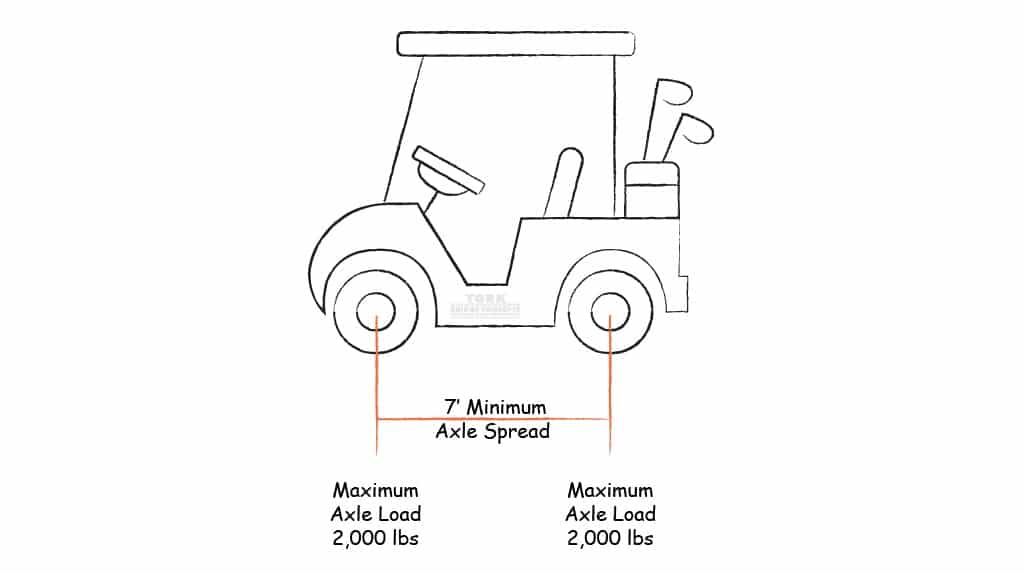
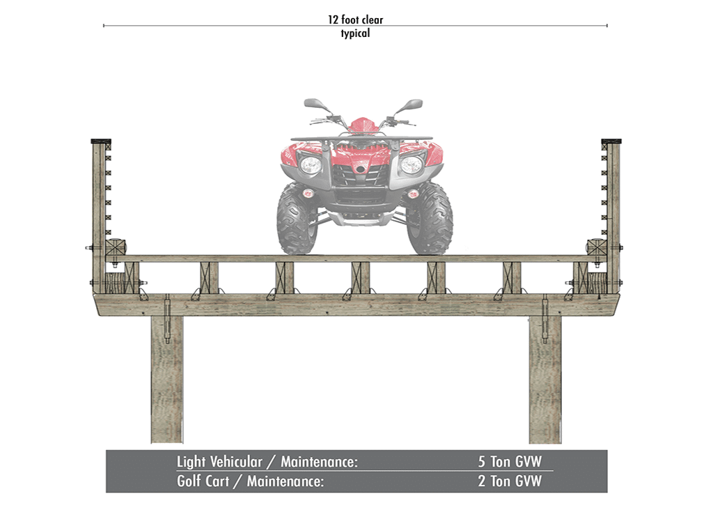
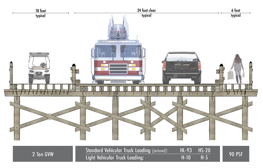
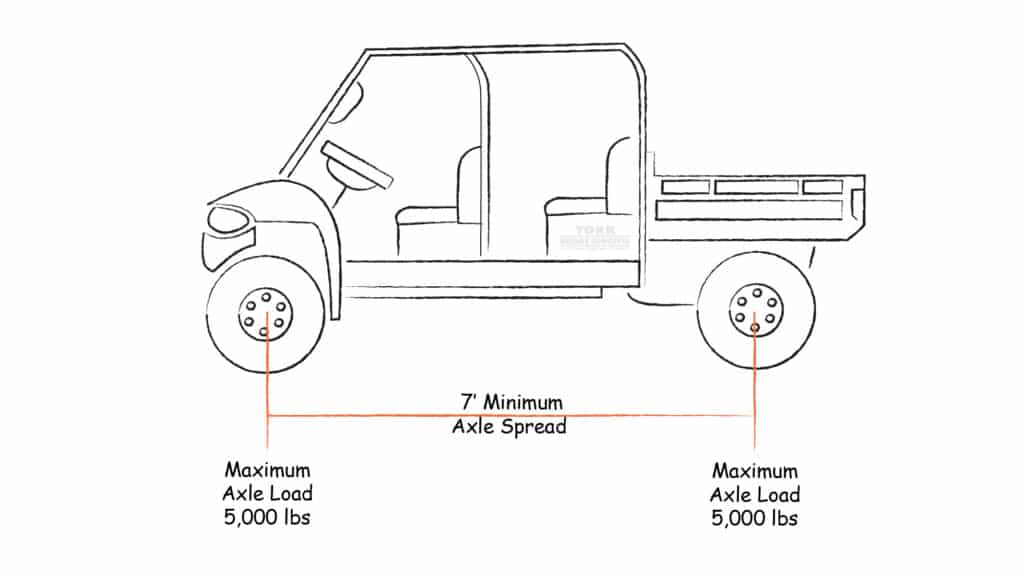
This category is based on a bridge that requires regular usage by a 6-person golf cart or utility terrain vehicle up to a small pick-up truck.

Load Capacity Axle Quantity Gross Vehicular Weight (GVW) Per Axle Loading
5 Ton GVW 2 axles Min 7' Axle Spread 5 kips (5k lbs) - 5 kips (5k lbs)
2 Ton GVW 2 axles Min 7' Axle Spread 2 kips (2k lbs) - 2 kips (2k lbs)
Timber Bridge Load Capacity Factors

  • Load capacities for vehicular bridges are determined based on the types of vehicles they are designed to support. This includes considerations for standard passenger vehicles, trucks, buses, and other specialized vehicles.
  • The load capacity is typically specified in terms of the maximum allowable weight that the bridge can safely support. This includes both static and dynamic loads.
  • Factors such as traffic volume, vehicle types, and the intended use of the bridge play a significant role in determining the appropriate load capacity.

Pedestrian & Boardwalk Loading Diagrams
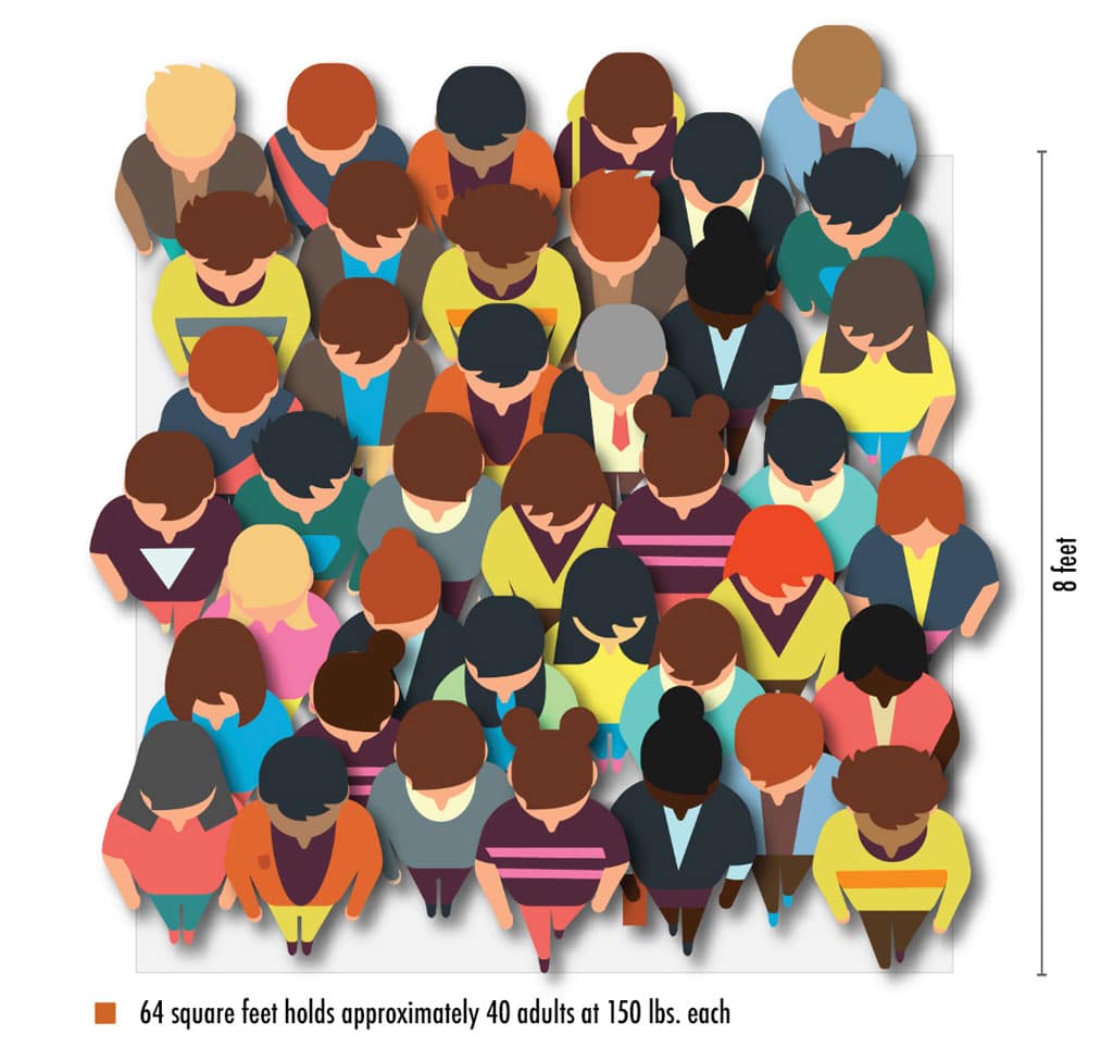
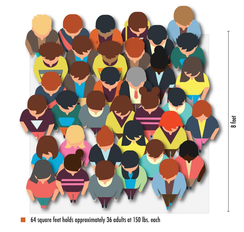
A pedestrian bridge is used to support the live load of one or more people. The 90 PSF loading capacity is based on regular usage of the bridge by pedestrians and cyclists. The 100 PSF loading capacity is based on regular usage of the bridge by pedestrians, cyclists, and event crowds. Sister loading can be utilized for occasional or emergency use. This could include occasional bridge use by golf carts, maintenance equipment, or vehicles. Ultimately, the additional or sister loading capacity is determined by the largest vehicle for anticipated use as a secondary loading. The most common complementary loading capacity includes the 2-ton or 5-ton GVW and the vehicular H5 or H10 loading capacities.

Safety & Regulation Factors For Timber Bridge Load Capacity

  • In both vehicular and timber bridges, safety factors are incorporated into the design to ensure that the bridge can handle loads well beyond the expected maximum. This provides an additional margin of safety to account for uncertainties and variations in actual usage.
  • Load capacities are subject to engineering standards, regulations, and building codes. Engineers must adhere to these guidelines to ensure that bridges meet safety and performance criteria.

Talk To An Expert